- 您现在的位置:买卖IC网 > Sheet目录3882 > PIC18F442T-E/ML (Microchip Technology)IC MCU FLASH 8KX16 EE A/D 44QFN
1997 Microchip Technology Inc.
DS30444E - page 101
PIC16C9XX
13.5
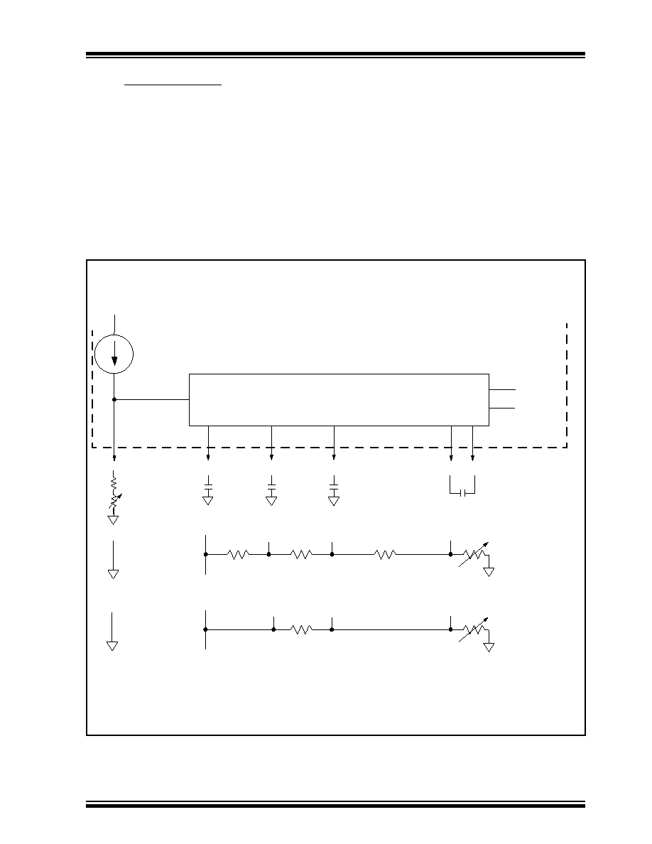
Voltage Generation
There are two methods for LCD voltage generation,
internal charge pump, or external resistor ladder.
13.5.1
CHARGE PUMP
The LCD charge pump is shown in Figure 13-13. The
1.0V - 2.3V regulator will establish a stable base volt-
age from the varying battery voltage. This regulator is
adjustable through the range by connecting a variable
external resistor from VLCDADJ to ground. The poten-
tiometer provides contrast adjustment for the LCD. This
base voltage is connected to VLCD1 on the charge
pump. The charge pump boosts VLCD1 into VLCD2 =
2*VLCD1 and VLCD3 = 3 * VLCD1. When the charge pump
is not operating, Vlcd3 will be internally tied to VDD. See
the Electrical Specications section for charge pump
capacitor and potentiometer values.
13.5.2
EXTERNAL R-LADDER
The LCD module can also use an external resistor lad-
der
(R-Ladder)
to
generate
the
LCD
voltages.
Figure 13-13 shows external connections for static and
1/3 bias. The VGEN (LCDCON<4>) bit must be cleared
to use an external R-Ladder.
FIGURE 13-13:CHARGE PUMP AND RESISTOR LADDER
C2
VLCD2
VLCD1
VLCD3
C1
VDD
VLCDADJ
10
A
Connections for
internal charge
pump, VGEN = 1
VDD
Connections for
external R-ladder,
1/3 Bias,
VGEN = 0
Connections for
external R-ladder,
Static Bias,
VGEN = 0
nominal
Charge Pump
LCDEN
SLPEN
0.47
F*
0.47
F*
0.47
F*
0.47
F*
10k*
5k*
10k*
130k*
100k*
* These values are provided for design guidance only and should be
optimized to the application by the designer.
发布紧急采购,3分钟左右您将得到回复。
相关PDF资料
PIC18LF4539T-I/ML
IC MCU FLASH 12KX16 EE A/D 44QFN
PIC18F452T-E/ML
IC MCU FLASH 16KX16 A/D 44QFN
PIC18F442-E/ML
IC MCU FLASH 8KX16 EE A/D 44QFN
PIC18F2539T-I/SO
IC MCU FLASH 12KX16 EE AD 28SOIC
PIC18F4439T-I/PT
IC MCU FLASH 6KX16 EE A/D 44TQFP
PIC16LF77T-I/ML
IC MCU FLASH 8KX14 A/D 44QFN
PIC16F74T-E/ML
IC MCU FLASH 4KX14 A/D 44QFN
PIC16F74-E/ML
IC MCU FLASH 4KX14 A/D 44QFN
相关代理商/技术参数
PIC18F442T-I/L
功能描述:8位微控制器 -MCU 16KB 768 RAM 34I/O RoHS:否 制造商:Silicon Labs 核心:8051 处理器系列:C8051F39x 数据总线宽度:8 bit 最大时钟频率:50 MHz 程序存储器大小:16 KB 数据 RAM 大小:1 KB 片上 ADC:Yes 工作电源电压:1.8 V to 3.6 V 工作温度范围:- 40 C to + 105 C 封装 / 箱体:QFN-20 安装风格:SMD/SMT
PIC18F442T-I/ML
功能描述:8位微控制器 -MCU 16KB 768 RAM 34I/O RoHS:否 制造商:Silicon Labs 核心:8051 处理器系列:C8051F39x 数据总线宽度:8 bit 最大时钟频率:50 MHz 程序存储器大小:16 KB 数据 RAM 大小:1 KB 片上 ADC:Yes 工作电源电压:1.8 V to 3.6 V 工作温度范围:- 40 C to + 105 C 封装 / 箱体:QFN-20 安装风格:SMD/SMT
PIC18F442T-I/PT
功能描述:8位微控制器 -MCU 16KB 768 RAM 34I/O RoHS:否 制造商:Silicon Labs 核心:8051 处理器系列:C8051F39x 数据总线宽度:8 bit 最大时钟频率:50 MHz 程序存储器大小:16 KB 数据 RAM 大小:1 KB 片上 ADC:Yes 工作电源电压:1.8 V to 3.6 V 工作温度范围:- 40 C to + 105 C 封装 / 箱体:QFN-20 安装风格:SMD/SMT
PIC18F4431-E/ML
功能描述:8位微控制器 -MCU 16KB 768 RAM 34 I/O RoHS:否 制造商:Silicon Labs 核心:8051 处理器系列:C8051F39x 数据总线宽度:8 bit 最大时钟频率:50 MHz 程序存储器大小:16 KB 数据 RAM 大小:1 KB 片上 ADC:Yes 工作电源电压:1.8 V to 3.6 V 工作温度范围:- 40 C to + 105 C 封装 / 箱体:QFN-20 安装风格:SMD/SMT
PIC18F4431-E/P
功能描述:8位微控制器 -MCU 16KB 768 RAM 34 I/O RoHS:否 制造商:Silicon Labs 核心:8051 处理器系列:C8051F39x 数据总线宽度:8 bit 最大时钟频率:50 MHz 程序存储器大小:16 KB 数据 RAM 大小:1 KB 片上 ADC:Yes 工作电源电压:1.8 V to 3.6 V 工作温度范围:- 40 C to + 105 C 封装 / 箱体:QFN-20 安装风格:SMD/SMT
PIC18F4431-E/P
制造商:Microchip Technology Inc 功能描述:IC 8BIT FLASH MCU 18F4431 DIP40
PIC18F4431-E/PT
功能描述:8位微控制器 -MCU 16KB 768 RAM 34 I/O RoHS:否 制造商:Silicon Labs 核心:8051 处理器系列:C8051F39x 数据总线宽度:8 bit 最大时钟频率:50 MHz 程序存储器大小:16 KB 数据 RAM 大小:1 KB 片上 ADC:Yes 工作电源电压:1.8 V to 3.6 V 工作温度范围:- 40 C to + 105 C 封装 / 箱体:QFN-20 安装风格:SMD/SMT
PIC18F4431-E/PT
制造商:Microchip Technology Inc 功能描述:IC 8BIT FLASH MCU 18F4431 TQFP44